Lab 6: The Internet of Things and Serial Peripheral Interface
Introduction
In this lab we were tasked with creating an Internet of Things (IoT) device that displayed the temperature of the lab when requested and could control an LED connected to our MCU.
Lab Overview
The goal of this lab was to learn how to tie together multiple different components in conjunction with our MCU to create the desired IoT device. We used an ESP8266 which is a Wi-Fi microcontroller with pre-written web server code to host webpage. The MCU would then communicate with the webpage over UART allowing the MCU to read and write data to the ESP8266 and change the webpage. The MCU would also communicate with a DS1722 Digital Thermometer over SPI, synchonously recieving temperature data and sending it over UART to the page.
The Temperature Sensor
This lab used a DS1722 Digital Thermometer described in the image below.
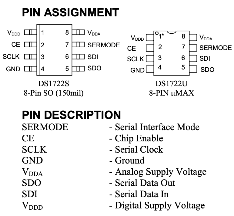
This sensor is able to communicate over both SPI and 3-wire, but in this lab we just used SPI. The MCU Pins were connected to the sensorsSCLK, CE, SDO, and SDI pins. When using SPI the sensor has the following registers.

The SPI system configured in this lab sent and recieved 8 bits of data. When reading the temperature from the sensor the MCU first writes the 8 bit read address (either 0x01 or 0x02) and then writes 0x0, it then reads what the sensor outputs. Since the sensor only outputs 8 bits but the temperature is sent over 16 bits you must call 0x01 and 0x02 which relate to the LSB and MSB data that need to be concatenated and then converted into a decimal temperature. On this temperature sensor you can also change the configuration depending on the level of resolution you want. When writing to the configuration register the MCU writes 0x80 first to tell the sensor the specific location and then writes the 8 bit configuration according to how many bits of precision you want for the next read.
MCU Design
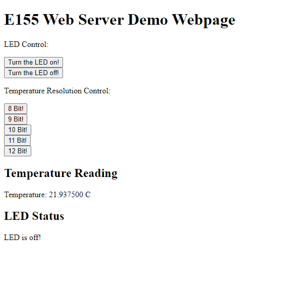
In this lab our MCU had two jobs. The first was to send data to the webpage over UART to tell it what to display and allow the webpage to send requests to the MCU. In the MCU source code the main function begins by sending the Wi-Fi chip some HTML code for a webpage inlcuding the temperature reading and configuration buttons as well as buttons to control the LED. When it does respond the MCU looks to see if it was a Temperature configuration request or LED request and then calls the respective code to either light up the LED or send an SPI signal to change the configuration register resolution and update the current temperature on the webpage.
MCU Pinout
Below is the pin configuration I used for this lab. The pin’s were relatively simple and just required making sure that specific pins with SPI alternate functions were available to conenct to the temperature sensor.

SPI SETUP
To setup up SPI on the MCU the we first had to configure the GPIO pins for MOSI, MISO, and SCK pins. We then configured CPI_CR1 including setting the baud rate, clock phase, clock polarity, full duplex, and setting the MCU to ast as the master. From there the amount of bits transfered on SPI was set to 8 bits and the frame format was set to SPI motorola mode.
After we succesfully initiatied SPI we had to make a function to read and write to the temperature sensor using SPI. In this function the program waited for the transmit buffer to be empty TXE and then sent accross the 8 bit message we wanted to transfer. One unique feature was that the data register that holds the SPI data is 16 bits instead of 8. This meant if we tried to write an 8 bit message to this register the rest of the bits would be zero. To ammend this a pointer to the register was created of type uint8_t and the 8 bit data was then copied to the location the pointer pointed to. The program would then wait until the recieve buffer was full RXNE and return the data in the recieve buffer as a char.
Calculations
The only calculation in this lab was calulating the decimal temperature from the 8 to 12 bit data we recieved from the sensor using the following conversion.

This sensor uses twos complement to signify negative numbers. To compute the first 8 temperature bits I simply would check if the first bit was high or low and then add the decimal representation of the next 7 bits to either 0 or -128. For the second set of 8 bits I would mask each bit and check if it was high or low and then add the appropriate fraction to the final temperature reading.
Testing
To test that the SPI was working, I used a external digital analyzer to monitor the MISO, MOSI, CE, and SCLK pins. the following are two examples of SPI in action. You can clearly see the standard SPI process, first chip enable is set high and then the register locations we want data from are sent over MOSI. Then 8 clock cycles later we get temperature data from MISO. After getting the temperature we needed chip enable is set low again.
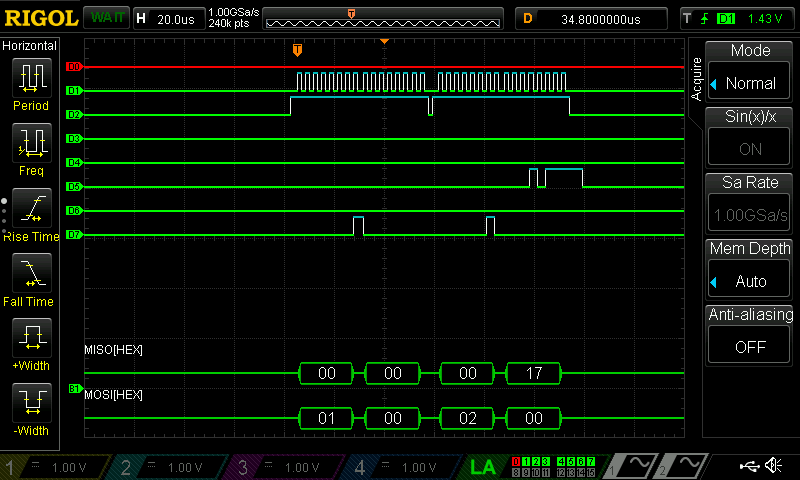
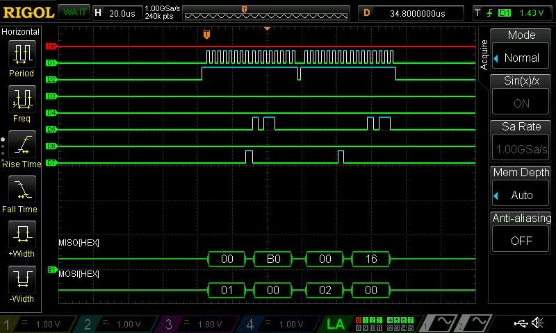
The first image shows the MCU reading both the 0x01 and 0x02 register. Since this is an 8 bit reading we get nothing from 0x01 and we get a value of 17 from 0x02 which correlates to a temperature of 23 celcius. The second image similarly reads the full temperature but since the sensor is configured for 12 bit resolution we see a reading of 0xB0 from register 0x01 and 0x16 from register 0x02 giving us a more accurate temperature of 22.6875 celcius. The logic analyzer turned out to be very useful as it allowed us to insight to what our hardware was doing in realtime.
Once the MCU temperature code finally was able to interface with the UART webpage it was time to validate. Launching the website in the digital design lab I found that the webpage would show a reading around 24 C which translates to 75 F. This is right around room temperature where I expected it to be and shows that the temperature converting function works well. One thing that was interesting is when trying to change resolution it often took two clicks to get the resolution to change. We believe this is because it was still changing the configuration and couldn’t fully convert the new temperature before our webpage requested it. I tried to fix this by adding a 1.2s delay, which corresponds to the conversion time of the highest resolution reading, but unfortunately our webpage would time out as it wasn’t getting data frequently enough.
Outcome
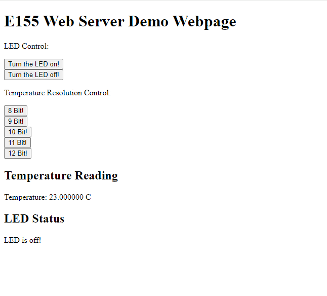
From the two images below you can see how the website has buttons to select the resolution of the temperature sensor. It also shows the webpage properly displaying temperature at the bottom of the page while keeping all the LED controls available and functional. On top of becoming more confortable using and initializing SPI, this lab provided a nice insight to how webpages work and how we can communicate with them using USART.
Time in Lab this week: 22 Hours